|
|
|
|
| Place mouse over 'Products > Screen Printing' menu above to display extra options |
| Page Location: Home > Training > Information Sheets > #39 Testing the SP-275 trigger switch |
|
|
|||
|
|||
|
|
|
|
|
|
| Place mouse over 'Products > Screen Printing' menu above to display extra options |
| Page Location: Home > Training > Information Sheets > #39 Testing the SP-275 trigger switch |
|
|
|||
|
|||
|
|
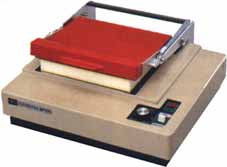 Testing
the Trigger Switch on the RISO SP-275 ScreenFax
Testing
the Trigger Switch on the RISO SP-275 ScreenFax
The following procedure should ONLY be done after contacting NEHOC for advice first. Any warranty will be void by the following action unless approved/ instructed by NEHOC prior.
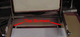 2.
At the top of the machine just behind the stage glass there are two screws
holding the back cover to the machine (they may be under warranty
stickers) - remove these
2.
At the top of the machine just behind the stage glass there are two screws
holding the back cover to the machine (they may be under warranty
stickers) - remove these
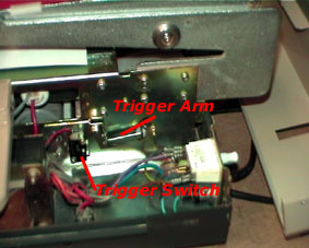
 What
the Trigger Switch should look like:
What
the Trigger Switch should look like:
7. Whilst looking at the Trigger Switch, lower the handle of the machine, just as if imaging a screen, so we can see what is happening to the Trigger Switch
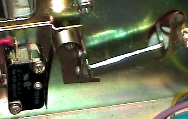
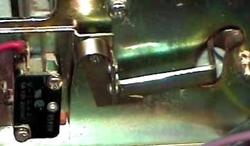
It should depress and activate the button - you will hear a tiny click.
When the Trigger Switch is depress it will look like the picture left.
Making Adjustments
If the switch is not working there are a few thing we can do - try the following in this order.
![]() Place
a drop of WD40/ RP7/ mechanical lubricant onto the button ONLY -
we are not spraying the button, just lubricating a little. This is preferred
first as we try to avoid adjusting the switch angle where possible.
Place
a drop of WD40/ RP7/ mechanical lubricant onto the button ONLY -
we are not spraying the button, just lubricating a little. This is preferred
first as we try to avoid adjusting the switch angle where possible.
![]() If the switch
is not bouncing back then the pressure from the Trigger Arm might be too great
and an adjustment on the Trigger Switch backing plate may be required
If the switch
is not bouncing back then the pressure from the Trigger Arm might be too great
and an adjustment on the Trigger Switch backing plate may be required
Adjusting the Trigger Switch Backing Plate
To the left of the Trigger Switch are two screws - it's the bottom screw that adjusts the angle of the plate.
As the Trigger Switch is sensitive, the degree of change is very minute and several attempts may be required before finding the optimum angle.
1. Release the pressure on the top screw slightly - not too much as it's the bottom screw that does all the work
2. Release the pressure on the bottom screw and adjust the angle
3. Tighten the screws and test the imaging by lowering the handle and pressing to move the Trigger Arm
4. Test the angle you have set by lowering the handle of the machine and performing a test flash (with the power off)
Testing the machine
With the adjustment made, we need to test the machine.
1. Plus the power cord back in to give the machine power.
When we removed the back cover, we disarmed the power supply by exposing the rear safety switch, so when the power is plugged in the machine will still be 'dead'.
2. Keep the back cover off at all times, however you will need to turn the machine on - either to PPC or NON-PPC (it doesn't matter). You will need to slide the front cover back for this to access the power switch.
 If
you remove the front cover DO NOT TOUCH ANY OF THE OTHER ELEMENTS AT THE FRONT
OF THE MACHINE!!!!!
If
you remove the front cover DO NOT TOUCH ANY OF THE OTHER ELEMENTS AT THE FRONT
OF THE MACHINE!!!!!
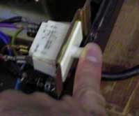
3. With the power on we not need to power up the machine by enabling the rear safety switch - you can do this by simply pressing it in with your finger - pictured right
You need to keep this depressed whilst testing until after your machine flashes, as if you release the pressure the power is cut off.
4. Once the machine begins to click 'OK' and ready for imaging, lower the handle and flash the machine
If the adjustment was correct you will receive a flash.
IMPORTANT - if you need to re-adjust the angle of the Trigger Arm again after testing with the power on - UNPLUG the power cord. Even through the rear safety switch disables the machine, you should ALWAYS use caution when handling high voltage electrical equipment.