|
|
|
|
| Place mouse over 'Training' menu above to display extra options |
| Page Location: Home > Training > Information Sheets > #36 Thermal Carrier Instructions |
|
|
|
|
| Place mouse over 'Training' menu above to display extra options |
| Page Location: Home > Training > Information Sheets > #36 Thermal Carrier Instructions |
|
|
|||
|
|
|||
|
|
|||
|
|
Thermal Carrier Instructions
In this example we use the VistaFax 1UF Model.
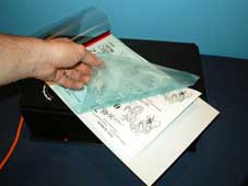
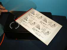 | Step 1 Artwork can be hand drawn, photocopied or a computer laser print - as long as it’s carbon based it will work. For details on artwork types - click here . . Lift the cover and place your artwork 'face up' inside the carrier. |
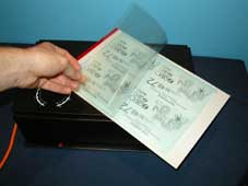 | Step 2 Cut your ScreenMaster to size and insert this into the carrier, over your artwork, with the film side [smooth] down against your artwork. Turn the machine on and feed the carrier into the front of the machine, it will ‘grab’ the carrier and feed it through out the back. Remove your imaged screen from the carrier and remove the artwork from the back of your imaged screen. |
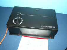 | Step 3 Turn the machine on to the required setting [5 is normally used for photocopies/ laser prints] and feed the carrier into the front of the machine. |
 | Step 4 The machine will ‘grab’ the carrier and pull it through, turning the heat element on as it passes through and push the carrier out the back of the machine. Remove your imaged screen from the carrier and remove the artwork from the back of your imaged screen. |
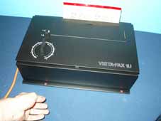
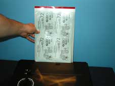 | Step 5 Support the carrier as it comes out the back of the machine. Do not pull it out/ through the machine, just support it's weight as it comes through. |
 | Step 6 Lift the cover and remove your imaged screen from the carrier. As pictured left, the screen has now been imaged. Check a corner to see the screen has been imaged correctly [you may need to adjust your setting if required].
|
With your screen now imaged you are ready to mount your screen to a frame and commence printing.
Repairs and Replacements
Thermal Carriers are exposed to difficult working conditions and may deteriorate quickly if not properly maintained and cared for. The high quality teflon cover should outlast both the backing sheet and joining tape.
The new carrier has been constructed for fast & easy onsite repair at low cost, rather than replacing the entire unit.
![]() New thermal joining tape is required for ALL repairs
New thermal joining tape is required for ALL repairs
Roll joining tape across a flat surface to a length of 25cm.
Place teflon cover over backing sheet and align the top edges
With cover and backing aligned, place the top edge halfway up the tape to attach the backing sheet to the tape - press firmly downwards to attach the tape
Fold the top of the exposed tape over the top of the teflon cover to join the pieces